Negative feedback is the basis for practical op-amp circuits.
Without negative feedback, the high-gain op-amp saturates and cannot amplify linearly.
Negative feedback feeds a portion of the output signal back to the inverting input, opposing the input signal. This achieves:
· Precise gain control, independent of open-loop gain
· Improved linearity and greatly reduced distortion
· Extended bandwidth and better noise immunity
· Stabilized output against temperature and component variations
Negative feedback makes the ideal op-amp a practical device.
Basic Op-Amp Configurations: Core Circuits & Formulas
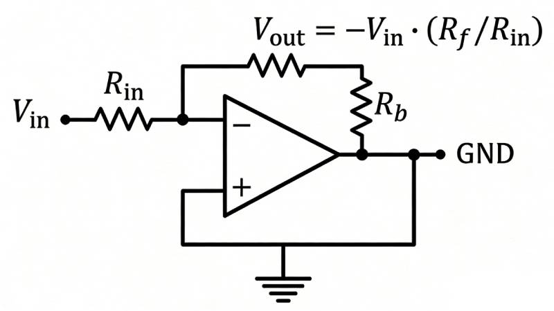
1. Inverting Operational Amplifier
The input signal goes to the inverting input.
Output is 180° out of phase with the input.
Voltage gain formula:
A_v = -frac{R_f}{R_{in}}
Key features:
· Gain can be positive or negative in sign
· Input impedance ≈ R_{in}
· Phase inversion
Typical uses: signal inversion, fixed-gain amplification, audio processing.
Illustration note:
Show circuit with:
· Signal source to R_{in} to inverting input
· R_f between output and inverting input
· Non-inverting input grounded
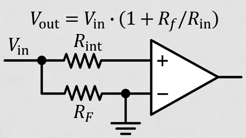
2. Non-Inverting Operational Amplifier
The input signal is applied to the non-inverting input.
Output stays in phase with input.
Voltage gain formula:
A_v = 1 + frac{R_f}{R_{in}}
Key features:
· Extremely high input impedance
· No phase inversion
· Gain ≥ 1
Typical uses: sensor preamplification, high-impedance signal acquisition.
Illustration note:
Show circuit with:
· Signal to non-inverting input
· R_{in} from inverting input to GND
· R_f from output to inverting input
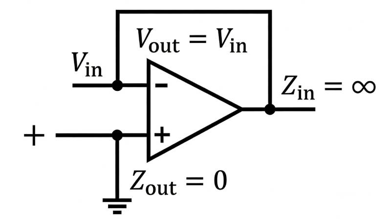
3. Voltage Follower (Buffer Amplifier)
A special case of the non-inverting amplifier with:
· R_f = 0
· R_{in} open
Voltage gain:
A_v = 1
Main purpose:
·Impedance matching
· Signal isolation
· Improve driving capability without changing amplitude
Typical uses: ADC input buffering, sensor output isolation.
Illustration note:
Show circuit with:
· Input directly to the non-inverting terminal
· Output connected directly back to the inverting terminal
4. Differential Amplifier & Summing Amplifier
Differential Amplifier
Amplifies the voltage difference and rejects common-mode signals.
Formula:
V{out} = frac{R_f}{R_{in}}(V_2 - V_1)
Foundation of instrumentation amplifiers.
Summing Amplifier
Algebraically adds multiple input voltages.
Used in signal mixing, calibration, and level-shifting circuits.
Real-World Op-Amp Behavior: Non-Ideal Characteristics
Ideal op-amps are theoretical. Real ones have non-ideal parameters that affect accuracy, stability, and frequency response.
Common Non-Ideal Parameters
· Input offset voltage: ~1–10 mV for general-purpose; μV-level for precision op-amps
· Input bias current: nA range (BJT), pA range (CMOS)
· Finite open-loop gain: ~100–140 dB, decreases at high frequencies
· -3 dB bandwidth: a few Hz to tens of Hz for general-purpose types
· Slew rate (SR): maximum output voltage change rate (V/μs)
· Finite input and output impedance
Practical Solutions to Reduce Non-Ideal Effects
· Offset voltage: use offset-null pins, external potentiometers, or precision op-amps
· Bias current: add balancing resistors to match the input resistance
· Bandwidth & slew rate: choose suitable op-amps for signal frequency
· Insufficient gain: use multi-stage amplification or high-gain devices
Op-Amp Applications: From Signal Conditioning to Advanced Systems
Signal Conditioning and Amplification
· Amplify weak sensor signals (temperature, pressure, photodiodes)
· Level shifting and impedance matching
· Filtering and noise reduction for small signals
Active Filters Using Op-Amps
Includes low-pass, high-pass, band-pass, and band-stop filters.
Advantages over passive filters:
· Provides gain
· Good impedance matching
· High precision
· Common topologies: Sallen-Key, multiple-feedback
Comparators and Oscillators
· Comparator: open-loop operation, compares voltages, used for threshold detection
· Oscillator: Wien-bridge (sine wave), relaxation (square wave)
Instrumentation Amplifiers
Built from three op-amps.
Features:
· High CMRR
· High input impedance
· Low noise
Used in precision measurement, medical monitors, and industrial scales.
Advanced Applications
·Current-to-voltage (I-V) converters
· Voltage-controlled current sources
· Voltage references
Example: photodiode conditioning.
System Design: Power, Grounding, EMI
· Use 0.1 μF decoupling capacitors near power pins
· Single-point grounding to avoid ground loops
· Shielding for high-frequency circuits to reduce EMI/RFI
 0
0

